Category Archives: Repairs

Repairs

Dataman S4 Programmer Part 1

Soon after I started out in electronics, I quickly began looking for a device that could program my own EPROMS / Memory from a computer. So when I started doing freelance work, I was able to purchase a Chinese HI-LO ALL02 programmer. The down side was that it required a slot in my PC for the ISA card, which then plugged into its external programmer. It wasn’t portable and it required the PC to do all the heavy lifting. I still thought this was amazing and it was used on many many projects, beginning in the late ’80s right up until the early ’00s. It paid for itself several times over but the only problem I have now, is that the ISA card for the programmer has gone missing (a suspected casualty of a spring clean). Still, I have the programmer and I’m actively looking for an ISA card for it.

When I joined Intermec Ireland, in the mid ’90s, we had a programmer in the service department which allowed us to program PROMs and EEPROMs via the serial port on the PC and while it was slow, it did work. It supported various devices and once the code was downloaded into the programmer, you could program multiple EPROMS in minuets. It made me realise the advantages of programmers with their own intelligence and memory.

At the same time, the various magazines that I was reading were advertising an EPROM programmer that I thought was perfect. It was battery powered and you could download firmware into it and use it in the field. It not only supported Memories, but Microcontrollers as well. To me, it was the Holy Grail of programmers. It had a display just like my beloved EPSON HX-20 and it could be connected to your computer, via an RS232 port. The programmer allowed the user to view/edit the contents of the memory before programming a device (this was something I had been doing manually to set serial numbers on new products). At that time, USB didn’t exist in commercial PCs.

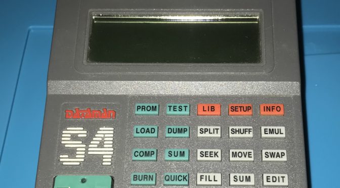
It was called the Dataman S4 and I wanted one, but there was one small problem, it was expensive, very expensive. I believe that it cost around £450 (€570), just for the basic model. As time progressed, I kept seeing this device in component catalogues from Radionics, and in Farnell, as well as the some electronic magazines. It was taunting me, saying please buy me, please buy me, but I could never justify the purchase. As more time progressed, and my requirements changed, I ended up getting high speed USB programmers instead, at a much lower costs, which supported more devices than the S4, but deep down, I still wanted an S4 programmer.

Recently when looking on www.adverts.ie, I found someone selling an S4, I couldn’t believe my luck! The price was right, it looked in great condition and it was pulled from a working environment. So I pulled the trigger, a deal was struck, and now it is mine. Am I happy? Yes I am. I now have a piece of equipment to add to my vintage equipment kit, that was on my wish list for many years.

Dataman S4 looking good.

As you can see it is in good condition, it’s clean and has very few marks on it. I did notice that the contrast control was not working and was flapping around inside. When I opened the unit, I discovered that the contrast control knob was broken off the contrast trimmer, so this will need to be fixed. The inside of the unit looks clean and original, which I was happy to see. The batteries look original, so these may need to be changed.

Inside the S4 programmer
Notice the centre pin of the contrast knob is stuck inside the contrast trimmer. This will need fixing.
Logic side, main PCB
512KB RAM

It looks as if no-one has been inside this device, so if it is faulty, I may be the first person trying to fix it. I have been informed that it was working and all it needs is a new 9VAC power supply. The HM628512 RAM Chip, on the bottom of the main PCB, is a 512K x 8 (4MB) RAM. So it looks as if the S4 programmer has the largest memory capacity available – another bonus!

Next Steps:
1) Find/purchase a 9VAC power supply for the programmer.
2) Download and setup drivers on the DOS/early Windows PC.
3) Test-program some EEPROM’s and PALs/GALs.
3) Fix the contrast control.

What are my plans for the Dataman S4?
I would like to use this programmer to program the firmware for the retro computer that is being built. I would also like to program the video character ROM and also maybe a GAL, for address decoding.

Electronic Repair, we need to change.

When thinking about electronics, what do you think about? Is it your laptop, your mobile phone, your fitness tracker or a home appliance? What happens when it breaks, what do you do? Do you bring it to a shop that can repair it? Can you find a shop that is willing to repair your device, or do you get told, it’s not designed to be repaired?

Have you had any of these questions?What are your options? Well, there was a time when on almost every street, there were repair shops where you could bring your faulty item in for repair. While, yes it could be expensive to get the item repaired, it could be repaired. The same is true today, but as a society we have become lazy and impatient. We want our stuff fixed instantly and we want it cheap! Oh yes, we cannot be without our beloved gadgets or appliances; we feel broken or incomplete. When we look into this further we have to ask the question, why? Why have we become so dependent on these devices? What is the social reasoning behind this?

One reason behind this is a technical addiction; yes the gadget may get us online for our social fix or endorphin rush when looking at the latest YouTube video, but at what cost?

I’m not going to discuss the pros and cons of being online, that’s a topic for others far more smarter than me to discuss. If our lives are going to be so dependent on being online, what are we going to do to ensure we’re able to get our fix, or make one gadget talk to another gadget? More importantly what are we going to do when it breaks? How important is it to us, really? If it’s that important, have we considered a backup plan? What to do when our primary gadget is no longer working?

If it’s that important that we have a backup, who will repair our beloved gadget? Can it be repaired and at what costs?

Personally I believe all items can be repaired to some level. This depends on the manufacture of the product, some vendors make it easy, some not so easy. While others will deliberately go out of their way to ensure the item cannot be repaired.

If you look at your car or your washing machine, both of these can be considered as gadgets and both can be repaired. Why is this so? The vendors understand that these gadgets will need to be maintained to keep operating. They make parts available for services centers to repair these gadgets. They also provide training to humans with a specific skill set, so they can perform these repairs.

Back in the early days of radio and TV it was very common for a family to purchase a kit form of one of these appliances, take it home, assemble it and get hundreds or sometimes thousands of hours of use before it needed a small repair; after which it would keep going until the next service or repair. This was very common up until the age of consumerism, where we were told we needed the latest gadget and needed it now and our previous gadget was obsolete. Or was it?

Yes, technology does evolve and move on. We have seen the disappearance of analogue TV, and very few new radio stations start broadcasting anymore. We now see digital TV, digital Radio, Internet Streaming of these services. These devices although more complicated than their earlier brethren can be repaired.

While repairing a vintage radio circa 1960’s, I discovered that the vendor had provided all the repair information inside a door on the radio. Why did they do this? It was because they knew, try as they may, some part would eventually fail and they wanted to give the customer the choice to perform the repair themselves. Yes, we were given a choice, repair it or take it to a shop who would repair it for us. As consumers we understood the value of these repairs and we had an idea how long it should take.

What about computers, I hear you say? Well recently I repaired a vintage BBC B Micro circa 1980’s, and again the vendor was able to provide the repair manual to allow these repairs to take place. This was common for most computers made in the ‘80s and ‘90s. There are still some computers that are repaired today for specialized industries.

In the 1990s, with the advancement in computers, they became modular, so you could swap out faulty components for working ones. Your faulty components could be sold/donated to companies who would perform these repairs. If you look at the more modern video card of today, which can cost thousands of euro, these are considered repairable by some companies.

Nowadays when our mobile phone breaks, we are told that it is not repairable. If you take five minutes and search on YouTube, I’m sure you will find someone who has performed a repair for the same fault that you identified with your gadget. So what’s wrong here?

As a society we have lost the skills to repair what we own. Some of these skills make take time to develop, but the more you do it, the better you become.

All I can say is to start small and work upwards, don’t try to repair your sister’s iPhone as your first repair attempt, unless you feel comfortable.

Let’s get back to being able to perform some basic repairs, instead of throwing that laptop or mobile phone in the bin. There may be someone out there who is prepared to put their time into repaiting that gadget for a charity. If you don’t want it, do the right thing and find it a new home. Let’s also think about the environment, just because your laptop doesn’t play high definition movies, it might be just right for someone learning about computers, who isn’t interested in multi-media.

If you can keep the gadget in circulation its not going into landfill; I’ve seen many laptops being thrown out with their batteries, containing lead and lithium going into landfill. What happens after, is that semi-state authorities are spending tens of thousands trying to remove these harmful materials from the waste. Where are they getting the money from? Us, we are the ones paying for this through our taxes; but if we all take a little bit of responsibility and think about what we are disposing, separate the harmful from the safe materials and the recyclable from the non-recyclable materials, we will be doing our little bit to help ourselves, our children and the environment.

And what of time and money? Your time and your money…ask yourself, are you one who is willing to spend cash on letting someone else perform the repair, and if so, how much is their time worth to them; if they spend four hours repairing your device are you willing to cover that cost? Do you value the service that this person is doing, or do you just want it cheap and don’t care about the cost? Ask yourself the same question if the situation was reversed. How would you feel?

Being a person who performs select repairs, I am choosy with my clients, as I have been on the receiving side of customers who would not pay for repairs, although I had spent many hours and purchased parts for their repair. It’s very disheartening as a technician, who takes pride in their work, not to be respected. It’s one reason why so many repair shops just close up and move on to other type of work. Yes, I do accept there are some cowboys out there, but in my experience they are only in the low percentages. It’s the consumers who have to step up and take responsibility for their actions, and value the work.

One way that consumers can take responsibility is to perform some basic repairs themselves. This, I have found, gives them a better understanding of what can go wrong with their gadget. This helps in two ways: firstly, when they take it to the shop, they will quickly identify the bullshit or when they are told mistruths about the repair; secondly, they will gain Insight into the effort required to repair their gadget.

One piece of advice I can give consumers when handing in their gadget for repair, is to be truthful with the technician. Tell them everything that happened, no matter how small, as the smallest piece of information may be all that is needed to change the repair time from six hours to one hour.

Rant over, hopefully this has given you some food for thought. It’s not everyone who wants to repair, but at least try to replace a plug on the next gadget you buy. Take the old plug off and keep it for next one (if not molded).

Speaker Cone Repair

While on the journey of repairing a vintage Ultra Electric R506 valve radio, one item that I left until the end was the repair of the speaker cone. Trying to find replacements (new old stock) for these devices is very hard and in most cases you end up taking parts from another unit (working or non-working). I try to avoid this practice, as this removes one more vintage radio from circulation.

In this speaker there were two nasty tears and a couple of holes in the paper cone. The centre of the speaker was intact, so that was a good starting point and I decided to attempt to repair the speaker cone.

In some cases replacing the cone would be the only option, but for this repair, I remembered an old trick that my father had used back in the late 70’s. As these old radios use a paper composite speaker cone, it is possible to repair some of the damage. Although it doesn’t look very pretty afterwards, the speaker will still be functional, and should sound better.

What you need is the following:

  1. PVA Glue.
  2. Paper towel (kitchen paper).
  3. Flat piece of wood (lolly stick).

Tear a piece of kitchen towel to cover the tear in the speaker (it should be about 1 cm wide to cover both sides of the tear).

Separate the plus of the paper towel and using just one ply, apply the PVA glue to the paper towel. Ensure the PVA glue covers all of the paper towel. I find it helpful to place the piece of paper on the top of a finger and then cover it with the PVA glue.

Carefully apply this piece of paper towel, with PVA glue, to the tear on the speaker. Using the flat side of the wooden stick, centre the piece of the paper towel over the tear. Spread the PVA glue over the edge of the paper towel on to the speaker cone. This will cause the fibres of the paper towel to break apart and become bonded with the paper in the speaker cone.

So, with my speaker cone, I patched the back where the tear in the paper was bad (as you can see below), to help reinforce the speaker. Once I patched the various holes and tears, it was left to dry for a day.

After a day, upon inspection, I could see that the PVA had dried and the repair was successful. When I checked the patches they still flexed when the speaker cone deflected, which was correct.

When I tested the speaker, it did sound much better than before. Although the speaker did not look very nice, it would be covered by the speaker grill in the radio chassis, so I decided not to spray the speaker cone with any paint.


Re-stuff Vintage Electrolytic Capacitors

In a recent repair, I experienced an issue where one of the main electrolytic capacitors in the radio had gone faulty. The radio was an Ultra Electric R506 circa 1945, and the capacitor was an old style can capacitor that had two capacitors in the one can. The can capacitor used the outside chassis as the common of the two capacitors (notice the red mark on the base of the capacitor that indicates one of the values of the capacitor).


As you can see from the marking this capacitor has two values, a 16uf and a 24uf capacitor (the 16uf capacitor is on the terminal with the red indicator).

While testing the part, I identified that one of the capacitors in the can had a value of 22.5uf, when it should have read 24uf. When I tested the capacitor for leakage, it was, so this will need to be replaced. 

The second capacitor in the can had a value of 7uf, where it should have had a value of 16uf. It was also leaking badly, so that capacitor will need to be replaced. 

I could have installed two new capacitors on the underside of the chassis and disconnected the terminals from the old can. While this would have worked it would not have looked professional. My other option was to re-stuff the capacitor can with two new capacitors (modern capacitors are smaller and should fit in the old style can).

I prised open the metal seal covering the terminal block, by inserting a small flat edge under the metal lip, and slowly working the way around the top of the capacitor. If you take your time with this step, you should be able to open the capacitor without tearing the metal of the seal.

Once opened, the next step was to disassemble the old capacitor and remove the old electrolyte and plates from the can. Once this was completed the next step was to prepare the old terminals for new capacitors I would install. I drilled out the rivets for the old terminals and disposed of these.

Following on from this, I built up the new terminal which was going  to mount the new capacitors and connections (for the capacitor). This new terminal was constructed from an M3 nut and bolt with a couple of solder tags, flat washers and a lock washer.

Once the old electrolytic capacitor was cleaned, a nut and bolt was used to attach a solder tag onto the inside of the capacitor. A wire was soldered to the solder tag that would then be connected to the common (negative) of the two new capacitors.

As 24uf capacitors are not a standard value, a 22uf/350V capacitor was used for the 25uf capacitor. A new 16uf/350V capacitor was used as a direct replacement for the old 16uf capacitor (both capacitors where high temperature 105 degree C variants).

In the above image you can see that the common (negative) of the two capacitors is connected to the wire/solder tag fitted inside the capacitor can.

Each of the positive leads of the two new electrolytic capacitors,  were soldered to the solder tags on the terminal block (note that the solder tag is on the outside of the terminal block to make it easier to connect the wires in the radio back to the capacitor).

Each of the terminals were colour coded to make it easier to identify the value of the terminals. The Blue terminal is the 22uf Capacitor, while the Red terminal is the 16uf Capacitor.

The terminal block was refitted into the capacitor can and the capacitor can was closed by slowly pushing the side walls in over the terminal block (as shown above). This was a slow process, as I did not want any creases in the metal (which tend to be problematic to remove).

Once the seal was closed over the terminal block, the capacitor was tested and then re-installed back into the radio.