Category Archives: HX-20 Computer

HX-20 – Build a new Charger

As the time has come to return back to the HX-20. I discovered that the original charger was no where to be found. So it is time to make a new charger for the HX-20.

In this video I will look at why I picked the power supply and show you how I wired up the 2.1mm DC Jack. We will also look at the basic charger circuit and why the power supply may appear incorrect at first, but why it has been selected.

At the end you will hear the HX-20 start, but we will see that there is no video and we will need to look at this is a later video.

HX-20 Battery Refit

After searching through my part bins, I was able to find a contact that I fitted into the connector for the battery pack, to replace the contact that was corroded. I fitted some spacers between each of the cell, then wrapped the battery pack in some tape to seal it.

Once the pack was assembled, it was fitted back into the HX-20. While reassembling the computer, I spotted a dry joint on the DC jack. So once again I disassembled the computer to remove the main PCB.

Once the PCB was out, I removed the DC jack, cleaned the contact for the DC jack, cleaned the pads on the PCB, reassembled the computer and tested it. The computer beeped when it was powered on, but I got no text on the LCD. So scratching my head, I disassembled the computer and checked the connectors. They all looked good. Then I remembered that the computer may need to be reset, as the battery had been out of the laptop for a few days.

So while the LCD was not showing anything when powered on, I remembered that you need to press “CTRL & @” to initialise the computer. After entering in a dummy date time of “01010101101” and pressing “Enter”, the computer reset and the LCD became active.

Yeah, the battery has been replaced and the computer is working again. 👍

Replacement Battery Pack for Epson HX-20

After disassembling the HX-20 the other day, and discovering that the Ni-Cad battery pack is leaking after 35 years,  I purchased some 2/3 C size cell rechargeable batteries. I purchased a total of 10 of these cells, as I plan to make a new battery pack for the HX-20 and one for a Epson PX-8’s that I also have. I suspect that if the batteries in the HX-20 are in this state then the ones in the PX-8 are not far behind.

Blog Post showing the teardown of HX-20.

Here is a link to these batteries on Amazon for those of you who want to replace their batteries in the computer.

After verifying that they were the correct size, I started to break apart the old battery pack to see how far gone  the batteries were. If you’re doing this at home, lay out some newspaper and wear gloves, as battery acid is nasty stuff.

Once I removed the yellow plastic shrink wrap from the battery pack, it was very clear that the protective foam on the negative side of the battery pack terminal was saturated (battery acid) and the terminal was corroded.

When the protective foam was released the lead to the negative side of the battery pack just fell off. It obviously hadn’t had a solid connection to the negative battery terminal for a long while.

Just to see how far the corrosion had gone, I cut into the wires going to the connector for the main PCB. I was unable to find any good clean tinned or copper wire – it was tarnished all the way to the connector. This means that I need make up a new connection going to the main PCB (I may just replace the headder  to the main PCB with PCB molex headder and replace the connection on the battery pack).

Curiosity got the better of me and I removed the last of the red shrink wrap on the old battery pack, just to see how bad the batteries were. The walls of two of the batteries were paper thin and were corroded in places completely. In fact I found two holes in the battery shells which are visible above. Can you spot them?  These batteries had seen better days and I was very happy that there were getting replaced.

It was very easy to wire up the new batteries. I just had to tack solder the positive lead of one cell to the negative lead of the other cell in series. Next step is to organise some spacers for in-between the cell, so the casings don’t short together, then to wrap the cells and install back in the computer.

– [Batt1] +  – [Batt 2] + – [Batt 3] + – [Batt4] +

We just have 4 x 1.2V Cells in series giving 4.8V. Once I get the new connectors for the battery pack and the main PCB. I’ll re-fiit the battery pack back in the HX-20, charge it up  and start testing.

** REMOVE BATTERIES FROM COMPUTERS GOING INTO STORAGE **

My HX-20

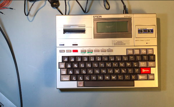
As promised, here is my working HX-20. I’ll strip it down for all to see, and then put it back together. I’ll run down though its specifications, and how it actually works. This model doesn’t have the expansion bay fitted, but I have an idea on this.

The HX-20 has a 20 column x 4 row LCD display. The contrast control on the right side of the computer is used to make the screen darker or lighter. It would be great if the unit had a backlight control – back in the day, that was helpful.  As the computer uses standard Hitachi display chipset, I should be able to swap it out for a model that has a backlight.

As you can see from this image, the tape on the driver is dated 1983. Yes the tape is 34 years old and it still works.

Once you remove the micro cassette drive, you then remove the seven screws from the bottom of the computer. Be careful when opening the case, as there is a flex connector that connects the display to the main PCB.

The main CPU is a 6301 running at .6MHz, with a second 6301 that manages the peripherals on the computer. The 6301 is a CMOS version of the 6801 Motorola Microcontroller.

When you release the flex cable from the main PCB, the two parts will open like a butterfly. The keyboard is connected to the main PCB  via two flex connectors located on the bottom of the main PCB – release the flex connectors by sliding the latch’s forward. You should find that the flex connectors are very easy to remove.

The RAM installed on the computer is static RAM which is backed up by the main Ni-Cad  battery. As the entire computer uses CMOS technology, it’s able to run off its internal rechargeable battery for up to 40 hours depending on use. Note: You won’t get 40 hours if you use the inbuilt printer or micro tape drive.

There are three screws that hold the inbuilt printer in place. Remove these screws and then release the catch for the printers flex cable on the main PCB. The printer should very easily lift out with no issue. Notice that I removed both the ribbon and paper from the printer before opening the computer.

Next, I removed the battery holding plate, by removing the screw that holds it in place. You will also need to slide the brown power connector to the left on the main PCB to release the battery from the computer. Notice the discolouration of the batteries in the shrink wrap. This is an early indication that these batteries are beginning to leak. Good thing I decided to open this computer at this time, otherwise I might never have noticed this and with the batteries leaking, they could have destroyed the computer. I’ll order some 2/3 C cells so I can build a new battery pack for the computer.

Once the battery is removed, there is only one screw holding the shield in place. Remove this screw and the shield should be easy to lift out.

You will notice that there are only four screws holding the main PCB in place. Once you remove these screws, lift the main PCB from the right side up. This will cause the 40 pin connector on the left side of the main PCB to slide out of its socket. The main PCB should lift out now.

Now the main PCB is out and we can see the two 6301 micro controllers, the 4 ROM’s in the sockets in the middle right of the PCB and the 8 x 2K RAM’s – 4 on the top right and 4 on the bottom right of the PCB.

Notice that the crystals used by both micro-controllers are 2.4576MHz. The instruction set codes for CPU use between 2-5 clock cycles per instruction. As an average, normally assume 4 clock cycles per instruction. This gives an average CPU speed of 614KHz. (0.49MHz to 1.22MHz).

On the left side of the computer is the expansion connector. The expansion unit allows for external RAM expansion if 16K. The expansion unit also has two sockets to allow installing other applications. The underside of the HX-20 had an expansion bay and when you open the bay there are four sockets that allow for ROM expansions.

The back of the computer has two DIN connectors. One is an RS232 serial port with speeds of up to 4800 baud. The second serial port is a high speed with baud rates of up to 38,400. This port is used for the external display controller and the serial floppy drive.

The power adaptor is centre negative, where most other power adaptors are centre positive. This is very important if you’re going to make your own power adaptors (if you lose your old adaptor). The adaptor should give 6.5v to 7.5v DC and be capable of supplying up to 200mA in current.

The micro cassette drive can be removed and a ROM cartridge can be installed in this slot. I have never seen one of these ROM cartridge units but I would be interested in finding one or getting a schematic of one to build my own ROM cartridge PCB.

And when it’s all put back together, it still works. The display wasn’t the best as the main battery was not fully changed. As mentioned above, I will replace the batteries with a new battery pack.

Epson HX-20

This was the first laptop computer that I ever used, after my Dad got one for his business. Having spent many Saturdays in the local computer shops, giving grief to the  sales teams and playing on friends’ computers, I was nominated to help my Dad setup and use this computer for his work. I spent many nights up late showing him how to use it and to this day, the noise of the built in printer is burnt into my brain (it was printing out results from the  data loggers that he sold).

The Epson HX-20 was unlike any other computer I had used before. With a flick of a switch, the unit came to life and I could start programming in Microsoft Basic. It was like the future had arrived.  None of the other computers I used back then were portable but I could sneak off to my room and write programs on the HX-20. After several weeks of pestering  my Dad for a micro-cassette tape of my own, he eventually gave me one and I was off.

I spent many weekends entering programs into the the HX-20 for various applications. Trying to debug programs on the small 20 Column by 4 Row display was a pain. Very quickly I learned to make sure that the entered syntax of the program was correct. At the time there was a magazine publication called INPUT, which contained programs for a section of the popular computers sold in the UK and Ireland.

After much trial and error, I eventually found that the code for the Dragon 32 computer was the most compatible with the Epson HX-20, as its version of Microsoft Basic was very similar.

The HX-20 was supplied with a basic 16K RAM. It had a 16K memory expansion bay which expanded the RAM to 32K. The program used 14K and an 8K buffer was allocated when the program was running. This left 10K for other programs. One of the tricks I learned very early on was how to save my Dad’s application to free up all the 32K RAM for my programs. When I finished playing with the computer at the weekend, I would load the application back on to the computer for my Dad, so it was back in the condition that I got it.

On the back of the HX-20, beside the power connector, there are two DIN connectors, one of which is a full RS232 interface. The RS-232 port supported most standard baud rates and data bits and parity. The high speed serial port is where the TV interface and the floppy disk drive connected to the HX-20. Never got either one of these devices (as much I wanted to have them) to make my life easier. Maybe there is a possible future project here…

Many years later I was given a present of a HX-20, which I have packed away. When I get a little more time, I’ll dig it out and will perform a tear down on it.


Technical Manuals Downloads

HX-20 Technical Support Manual

HX-20 Quick Reference Guide

HX-20 Technical Manual (Interfaces)